1. PRODUCTION METHOD
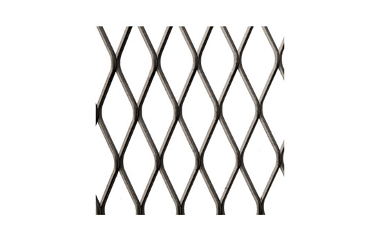
METAL DEPLOYAGE is produced by embossing (tearing) sheet metal and shaping it in sections beyond the deformation limit, so that it looks like a grid.
Depending on the shape of the cutting and shaping tools, loops are formed


rhomboid or hexagonal
There is no gluing or knitting anywhere.
2. DEFINITION
Based on the specifications of IN 791, the dimensions that determine each type of METAL DEPLOYMENT are the following:
Based on the specifications of IN 791, the dimensions that determine each type of METAL DEPLOYMENT are the following:
A = n long diagonal of the rhombus P width of the hexagon.
B = n small diagonal of the rhombus Π height of the hexagon.
π = the thickness of the metal.
λ = the width of each side of the rhombus Π hexagon.
B = n small diagonal of the rhombus Π height of the hexagon.
π = the thickness of the metal.
λ = the width of each side of the rhombus Π hexagon.
Dimensions are expressed as:

A – in millimeters (mm)
B – in millimeters (mm)
π – in tenths of a thousandth
l – in tenths of a thousandth
B – in millimeters (mm)
π – in tenths of a thousandth
l – in tenths of a thousandth
Prefix P defines Rhombus
Prefix H defines hexagon
n reference order of magnitudes
in the code is
Prefix (P P H), A, B, p, l.
Prefix H defines hexagon
n reference order of magnitudes
in the code is
Prefix (P P H), A, B, p, l.
3. AVAILABLE SHEET SIZES

METAL DEPLOYAGE is available in sheets according to the standard sheet dimensions, i.e.:
1mx2m
1,25m χ 2,5 m
1.5 m x 3.0 m with a length tolerance of 2%.
The width is always mentioned first in the descriptions.
Other sizes can be produced upon request.
1mx2m
1,25m χ 2,5 m
1.5 m x 3.0 m with a length tolerance of 2%.
The width is always mentioned first in the descriptions.
Other sizes can be produced upon request.
4. WEIGHT PER M2
The weight per sq. measure can be calculated with the formula:
The weight per sq. measure can be calculated with the formula:
WEIGHT = γ x 2λ x π /100 x B (where γ = specific gravity of the material)
5. METAL DEPLOYAGE, apart from all its other uses, can also be used for passable surfaces such as stairs, corridors, floors, lofts, etc. In these applications there are specifications that dictate as a maximum deflection arrow of the material, 1/200 of the opening (width) L of the passable surface.
And in order to take advantage of the maximum strengths, special attention must be paid to the following points:
And in order to take advantage of the maximum strengths, special attention must be paid to the following points:
α. The sheets of METAL DEPLOYAGE should be placed at the same time
RIGHT
Error 
β. The edges of the METAL DEPLOYER must press on the
bearing structure at least 30 mm wide.
B=30 mm minimum

Metal Deployment (Expanded)

|
CODE | 
|
CODE | Γ | |||||||||||||||||
| RHOMBUS DIMENSION | 2.4 x 1.6 | RHOMBUS DIMENSION | 28 x 10 | ||||||||||||||||||
| MAX WIDTH | 0.50m | MAX WIDTH | 1,00m | ||||||||||||||||||
| MATERIAL | ALUMINUM | MATERIAL | ALUMINUM + IRON | ||||||||||||||||||
| AVAILABLE THICKNESSES | 0.4mm | AVAILABLE THICKNESSES | 1 | ||||||||||||||||||
| WEIGHT M2 | WEIGHT M2 | ||||||||||||||||||||

|
CODE | 
|
CODE | A | |||||||||||||||||
| RHOMBUS DIMENSION | 6 x 3 | RHOMBUS DIMENSION | 10 x 5 | ||||||||||||||||||
| MAX WIDTH | 1,00m | MAX WIDTH | 1,00m | ||||||||||||||||||
| MATERIAL | ALUMINUM + IRON | MATERIAL | ALUMINUM + IRON | ||||||||||||||||||
| AVAILABLE THICKNESSES | 0.4/0.5/0.8 | AVAILABLE THICKNESSES | 0.7/07/1 | ||||||||||||||||||
| WEIGHT M2 | WEIGHT M2 | ||||||||||||||||||||

|
CODE | 
|
CODE | H 45 | |||||||||||||||||
| RHOMBUS DIMENSION | Decorative | RHOMBUS DIMENSION | 45 x 15 | ||||||||||||||||||
| MAX WIDTH | 1,00m | MAX WIDTH | 1,50m | ||||||||||||||||||
| MATERIAL | ALUMINUM | MATERIAL | IRON | ||||||||||||||||||
| AVAILABLE THICKNESSES | 0.7mm | AVAILABLE THICKNESSES | 3 | ||||||||||||||||||
| WEIGHT M2 | 1.1Kg | WEIGHT M2 | 10.5 Kg/M2 | ||||||||||||||||||
|
CODE |
|
CODE | P 40 | |||||||||||||||||
| RHOMBUS DIMENSION | 18 x 8 | RHOMBUS DIMENSION | 45 x 23 | ||||||||||||||||||
| MAX WIDTH | 1,00m | MAX WIDTH | 1,50m | ||||||||||||||||||
| MATERIAL | ALUMINUM + IRON | MATERIAL | IRON | ||||||||||||||||||
| AVAILABLE THICKNESSES | 0,7/1 | AVAILABLE THICKNESSES | 3 | ||||||||||||||||||
| WEIGHT M2 | WEIGHT M2 | 10.5 Kg/M2 | |||||||||||||||||||
| CODE | P 60 | CODE | H 115 | ||||||||||||||||||
| RHOMBUS DIMENSION | 60 x 25 | RHOMBUS DIMENSION | 115 x 30 | ||||||||||||||||||
| MAX WIDTH | 1,50m | MAX WIDTH | 1,50m | ||||||||||||||||||
| MATERIAL | IRON | MATERIAL | IRON | ||||||||||||||||||
| AVAILABLE THICKNESSES | 3/4/5 | AVAILABLE THICKNESSES | 4/5 | ||||||||||||||||||
| WEIGHT M2 | WEIGHT M2 | ||||||||||||||||||||

|
CODE | P 80 | 
|
CODE | P 110 | ||||||||||||||||
| RHOMBUS DIMENSION | 80 x 40 | RHOMBUS DIMENSION | 115 x 50 | ||||||||||||||||||
| MAX WIDTH | 1,50m | MAX WIDTH | 1,50m | ||||||||||||||||||
| MATERIAL | IRON | MATERIAL | IRON | ||||||||||||||||||
| AVAILABLE THICKNESSES | 2,5/3/5 | AVAILABLE THICKNESSES | 3/5 | ||||||||||||||||||
| WEIGHT M2 | WEIGHT M2 |


